DS21503 Rev. 9 - 2
1 of 3
1.5KE6V8(C)A - 1.5KE400(C)A
www.diodes.com
„
Diodes Incorporated
Maximum Ratings
@ T
A
= 25∞C unless otherwise specified
1.5KE6V8(C)A - 1.5KE400(C)A
1500W TRANSIENT VOLTAGE SUPPRESSOR
∑
1500W Peak Pulse Power Dissipation
∑
Voltage Range 6.8V - 400V
∑
Constructed with Glass Passivated Die
∑
Uni- and Bidirectional Versions Available
∑
Excellent Clamping Capability
∑
Fast Response Time
∑
Case: Transfer Molded Epoxy
∑
Case material - UL Flammability Rating
Classification 94V-0
∑
Moisture sensitivity: Level 1 per J-STD-020A
∑
Leads: Axial, Solderable per MIL-STD-202
Method 208
∑
Marking: Unidirectional - Type Number
and Cathode Band
∑
Marking: Bidirectional - Type Number Only
∑
Approx. Weight: 1.12 grams
Features
Mechanical Data
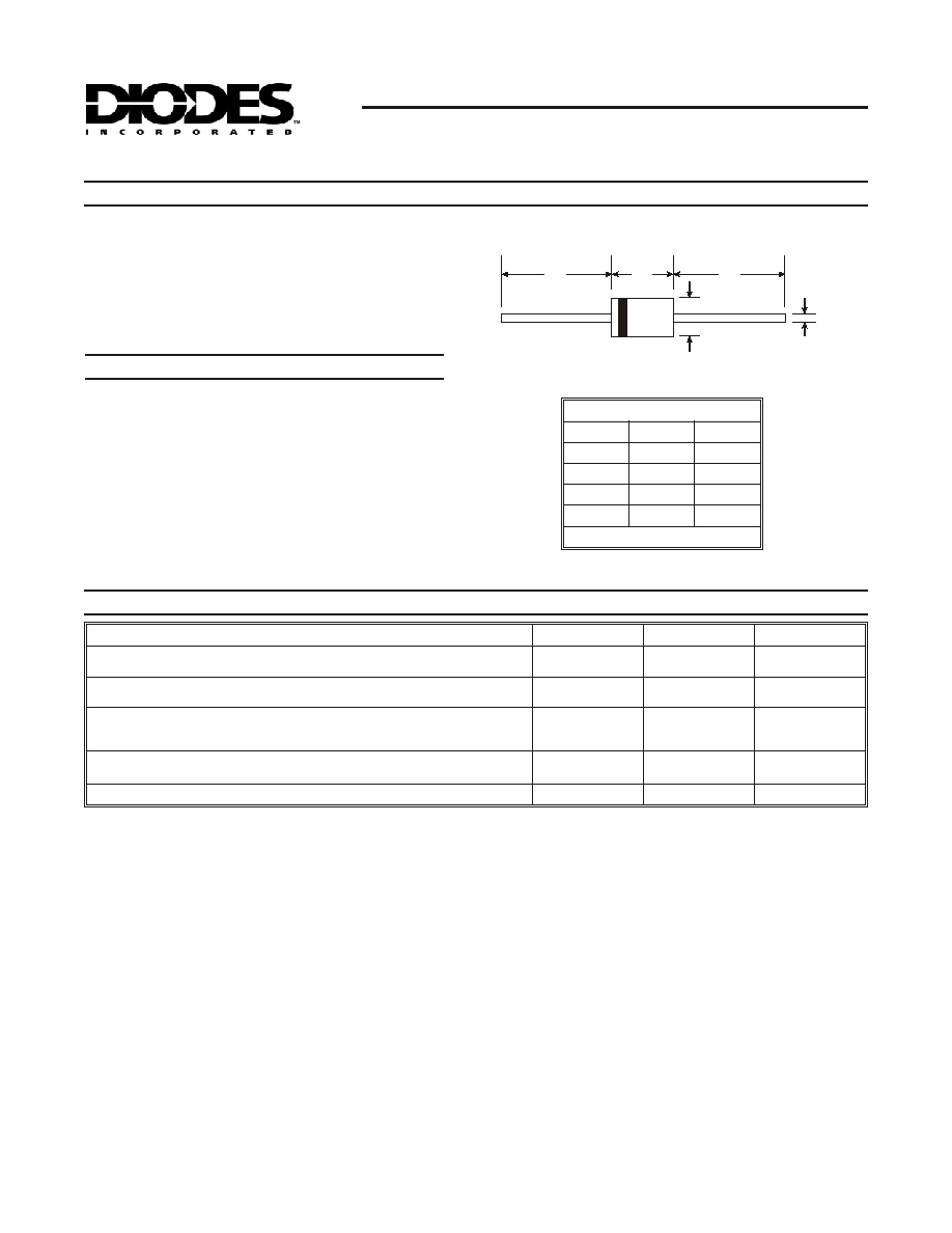
DO-201
Dim
Min
Max
A
25.40
--
B
8.50
9.53
C
0.96
1.06
D
4.80
5.21
All Dimensions in mm
A
A
B
C
D
Notes:
1. Suffix `C' denotes bi-directional device.
2. For bi-directional devices having V
R
of 10 volts and under, the I
R
limit is doubled.
Characteristic
Symbol
Value
Unit
Peak Power Dissipation at t
p
= 1.0ms
(Non-repetitive current pulse, derated above T
A
= 25∞C)
P
pk
1500
W
Steady State Power Dissipation at T
L
= 75∞C Lead Lengths 9.5 mm
(Mounted on Copper Land Area of 20mm
2
)
P
d
5.0
W
Peak Forward Surge Current, 8.3 Single Half Sine Wave Superimposed on
Rated Load (8.3ms Single Half Sine Wave,
Duty Cycle = 4 pulses per minute maximum)
I
FSM
200
A
Forward Voltage @ I
F
= 50A 300µs Square Wave Pulse,
V
BR
£ 100V
Unidirectional Only
V
BR
> 100V
V
F
3.5
5.0
V
Operating and Storage Temperature Range
T
j,
T
STG
-55 to +175
∞C

DS21503 Rev. 9 - 2
3 of 3
1.5KE6V8(C)A - 1.5KE400(C)A
www.diodes.com
1.0
10
100
0.1
1.0
10
100
1000
10,000
P
,
PEAK
PULSE
P
OWER
(kW)
P
T = 25∫C
C
IMPULSE
SINE WAVE
SQ. WAVE
10 X 1000 Waveform
as defined by REA
0
25
50
75
100
125
150 175
200
100
75
50
25
0
T , AMBIENT TEMPERATURE (∞C)
A
Fig. 4 Pulse Derating Curve
PEAK
PULSE
D
ERA
TING
(
%
PEAK
PWR
O
R
C
URRENT
)
L = 9.5 mm
40 x 40 x 1 mm Cu
0
25
50
75
100
125
150
175
200
0
1.25
2.5
3.75
5.0
T , LEAD TEMPERATURE (∞C)
L
Fig. 5 Steady State Power Derating
P
,
STEADY
S
T
A
T
E
POWER
DISSIP
A
TION
(W)
d
Single Phase
Half-Wave 60Hz
Resistive or
Inductive Load
0
1
2
3
100
50
0
I
,
PEAK
PULSE
CURRENT
(%I
)
Pp
p
Peak Value I
pp
Half Value I /2
pp
10 X 1000 Waveform
as defined by R.E.A.
t
p
t, TIME (ms)
Fig. 1 Pulse Waveform
1
10
100
1000
10
100
1000
10,000
V
, REVERSE STANDOFF VOLTAGE (V)
RWM
Fig. 2 Typical Total Capacitance
C
,
CAP
A
CIT
A
NCE
(pF)
T
Measured at
Stand-off Voltage
Measured at
Zero Bias


